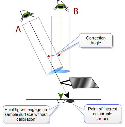
Without correction, there would be an offset between what the user sees in The Video Panel of the Setup view and the actual relationship of the tip to the sample, as illustrated in the figure below.
Figure 1: Actual (A) and Perceived (B) Relationship Between Optics and Tip and Sample Surface
In Figure 1, B indicates the perceived relationship of optics, tip, and sample surface. However, the user is actually observing the tip and sample along path A, which gives the erroneous impression that the tip is over the point of interest. Without calibration, upon engage the cantilever will move in a vertical line to the spot directly beneath it on the sample surface, missing the point of interest.
When calibrated, the software knows to offset the angle of engage from vertical, such that the tip lands on the point of interest on the sample.
|
|
To access the Colinearity Calibration function go to Calibrate > Optical > Optics/SPM Axis Co-linearity... This activates the Calibrate Axis Colinearity view: |
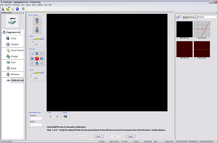
The Axis Colinearity Calibration Procedure is given in a series of step-by-step instructions at the bottom of the window.
| www.bruker.com | Bruker Corporation |
| www.brukerafmprobes.com | 112 Robin Hill Rd. |
| nanoscaleworld.bruker-axs.com/nanoscaleworld/ | Santa Barbara, CA 93117 |
| Customer Support: (800) 873-9750 | |
| Copyright 2010, 2011. All Rights Reserved. |